Case Study of oil and gas process piping and equipment inspection and CUI Discovery.
By Daniel Lillas Fabric Maintenance Coordinator, ACA, NACE Coating Inspector, ICORR PFP & Insulation Inspector.
Introduction
Corrosion under insulation (CUI) poses great risk for industrial plants, oil & gas and petrochemical facilities. CUI has proven difficult to manage due to the restrictions in inspection methods on live operating systems, often leading to planned and unplanned shutdowns and inspection programs being conducted as opportune scopes during short shutdown periods and often removal of insulation by visual inspection is the only option, placing further schedule pressures on inspection and maintenance teams.
There are many inspection techniques that provide some level of assurance however the most accepted method within the industry is close visual inspection (CVI), and in most cases leads to growth of scope once the outer weather jacketing has been removed, and the extent of damage only then becomes evident.
Systems that are susceptible to CUI can also lead to false assumptions when inspection programs are put together. The theory of CUI ranges in carbon steel are generally systems operating between -4°c to + 149°c. However many variances in operational conditions can lead to CUI outside of this range, items such as micro-climatic conditions, cyclic conditions, frequency of maintenance, external forces against piping systems, materials selection, insulation systems, condition of insulation and inconsistencies with documented operational conditions compared to actual operational conditions.
Case Study
The systems identified for the corrosion environment for part 1 of the case study are systems on an offshore oil and gas platform, located in tropical waters off Australia and subjected to monsoonal climates, high humidity, high ambient temperatures and a close proximity to the water level (~18mtrs).
The following system was inspected on the platform:
Glycol system ( for dehydration) operating from +30°c to +250°c and contained drains, deadlegs, straight run piping and complex configurations within a dedicated vendor supplied package.
The system was subjected to a large scale asset integrity inspection program along with all other piping systems on the facility. During the inspection program all piping systems were walked and catalogued for corrosion threats and visible areas of corrosion. Each location of corrosion was graded from minor (grade A) to severe (grade D).
On completion of grading, cataloguing and tagging all corrosion locations were assessed for severity and further inspection techniques were employed such as Ultra-Sonic thickness (UT) inspection, Radiography to further asses wall loss and operability of the system.
The insulated systems on the platform were subject to the same inspection program, however due to the inability to perform CVI because of the weather jacketing, standard inspection techniques were employed by targeting selected locations and systems that were assumed to be susceptible to corrosion. The technique however can be flawed with a “Hit & Miss” type of approach. Real time radiography was also used in an effort to identify dark spots or sections of interest, which had limited success on the acoustic insulated systems (mass loaded vinyl sheeting interfered with the process), and finally thermal imaging camera techniques.
All relied on the inspection and maintenance teams judgement of system and points of interest for success.
The Glycol system in the particular vendor skid had only a few points that were uncovered at the initial inspection and failed to uncover any significant corrosion concerns, predominantly the piping that was operating above the suspected CUI range ≥140°c was only inspected at low points for tell-tale signs of corrosion staining on the outer jacketing.
The system was coated originally in construction with Thermal Sprayed Aluminium (TSA) and silicone aluminium sealer. Field joints and ancillary fittings during construction were repaired using high temperature epoxy coatings.
The insulation code of Personal protection (hot) consisted of a single 25mm layer of mineral wool and metallic outer weather jacket.
Findings.
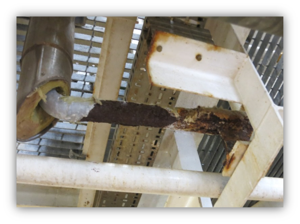
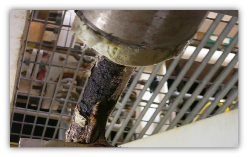
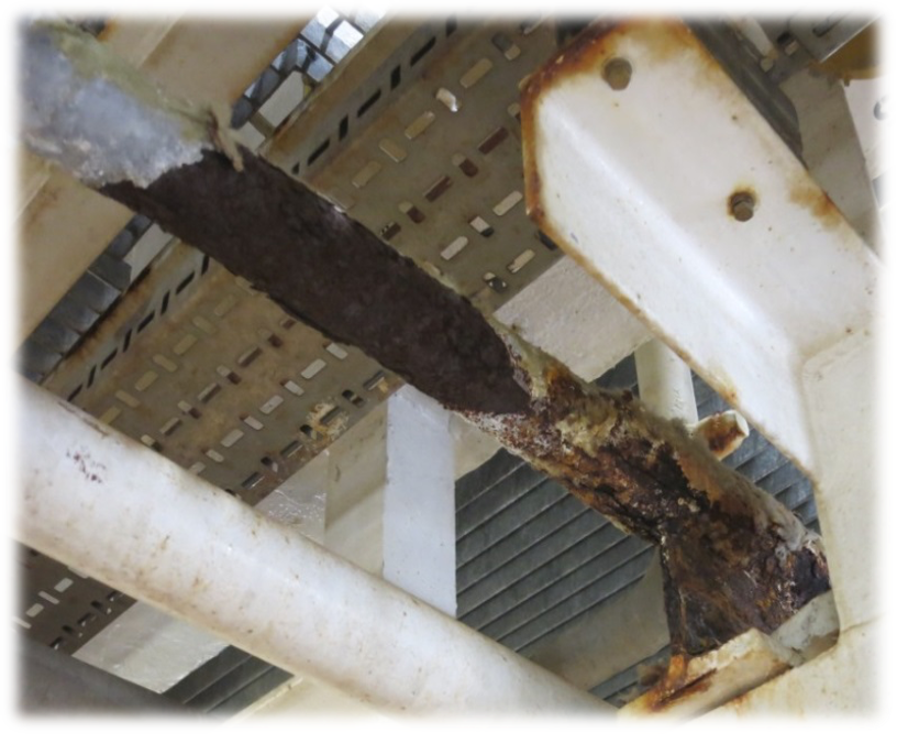
During routine inspections around the area on adjacent pipes the asset integrity inspectors identified some further possible corrosion areas by tell-tale corrosion signs on the external of the weather jacketing, upon removal a discovery of extensive corrosion activity and coating failure, on previously missed inspections as the pipe was operating at ~204°c, 0.5 bar pressure. The severe corrosion on the line prompted an immediate rethink on the inspection methodology and further investigation on the surrounding piping within the skid.
Little understanding of the corrosion mechanisms was identified at the initial inspection phase, only after close visual inspection and subsequent wall thickness inspections did the reality of the situation raise awareness to the true CUI consequences. Previously only minor CUI results were identified, mostly coating breakdown at welds and protrusions with minimal wall thickness loss.
The findings were significant and material loss in a relatively short life cycle of ≤10 years. 8mm wall thickness pipe on completion of radiography identified <1mm wall thickness at specific locations and a pipe replacement was implemented.
The costs to execute a scope of this nature on an operating gas facility are generally high, with partial shutdown of systems, reduced production, and labour intensive work using valuable bed allocation.
What went wrong?
From the original construction phase the selection of coating system may have been questioned, however might only been a contributing factor, the selection of surface preparation and coating repairs could also be thrown into the mix as a contributor, but the largest point of impact was the miss-understanding of what poses a risk for CUI and what doesn’t. As the system isometrics stated operating temperatures ~204°c the inspection program had overlooked the service as a threat.
The actual operating temperatures were cyclic and between the range of ~140°c to ~180°c due to process performance and various other process conditions. The influence of water ingress into the mineral wool over extended periods were also not understood, as the thought process of the surface temperatures of the pipes would dry any trapped moisture out and not pose a risk of CUI.
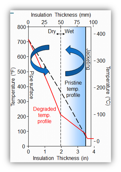
The mineral wool over time soaked up water (through rain, humidity, wash-down, and deluge) and created a convection cell driving moisture from the hot surface through the mineral wool, and once the moisture contacts the underside of the cooler jacketing it then condenses and starts the wetting cycle again by soaking into the insulation¹. This phenomenon was not understood at the time of initial inspections and further inspections on the similar systems uncovered comparable results.
Lessons learnt
Although the failure modes and potentials of CUI are generally well understood within oil & gas, processing and refining industries the lessons learnt from incidents and failures are not always acknowledged by other facilities.
The second part of the case study looks at a newly constructed LNG facility located in Australia and identifies some of the common design issues that can lead to CUI and failures, and comparing to previous industry failures and lessons learnt. The facility is subject to coastal marine environment, high ambient temperatures; generally lower humidity and low rainfall, however subject to seasonal cyclonic and monsoonal storms.
The facility followed some similar patterns as the offshore facility in the above situation; it was constructed outside of Australia, tight construction schedule, tight economical market and material selection challenges.
The newly constructed facility has common potentials with hot insulation, cold insulation, and acoustic insulation, although the data is not available and somewhat of a “crystal Ball” approach needs to be used based on previous findings from the offshore facility being in operation for over 10 years the signs can be considered the same. Items such as; field welded items that were repaired in unfavourable weather conditions (high humidity, rain, extreme weather climates hot / cold), material selection of insulation and coatings, design of pipe shoe and structural interfaces.
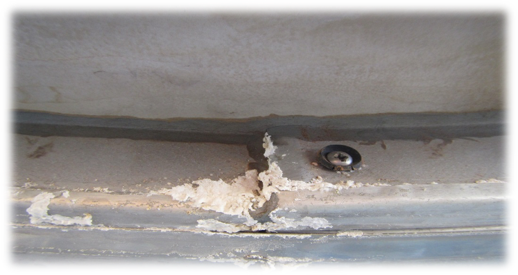
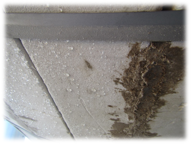
Early detection during construction identified water ingress into an insulated vessel, staining and leaching clearly visible-Photograph 3. Upon removal of the weather jacket, saturated perlite was identified. Heat transfer Cement products were also saturated, and staining of the internal surface of the weather jacket was evident. The vessel designed to operate at high temperatures between ~127°c -~240°c as a heat exchanger and specified insulation thickness of 63mm single layer of Perlite block
The Insulation although drying might have occurred during operation was removed and replaced, due to the risk of convection of any trapped moisture setting up a cycle. The relationship between the older existing offshore facility and the newly constructed facility is the CUI potential in systems that are deemed outside of the optimal temperature range, again sometimes little is understood by designers that the CUI can happen even in equipment operating in hot temperature ranges above the ~150°c if the mechanisms are present. Although every effort is made to prevent moisture from entering insulation it is sometimes inevitable that eventually water will find a way into the insulation material.
Conclusions.
As we continue to design new plants using new technology, insulation systems need to evolve with the technology, newer technology in insulation with superior hydrophobic properties and coatings with intricate formulations are often excluded from materials selection due to the sensitivity around costs, as these materials have generally higher initial outlay costs, however proven over time would be in most cases a savings and payback the initial spend by reducing invasive maintenance.
The fight against CUI is a complex one, the use of coatings, the type of insulation materials, the inspection methods, frequency and maintenance programs all contribute to the equation.
However in general the use of water absorbent materials in most processes will help promote CUI, than those materials that offer water repellent properties. Conventional wisdom as it might appear does not always transpose to designers or maintenance teams. The understanding of where to look for problems again is also a point of contention, low points, and bottoms of pipes, unfortunately it is not that simple, and even straight sections of pipes can be subject to localised CUI, with catastrophic results.
Acknowledgements
- Chauviere.M-“How selection of insulation material affects: Installation costs, Risk of CUI, and thermal losses” presentation March 2013.
- Smallridge G.- acknowledgement for supply of photographic references, & process data.
- Aerogels Australia, Caric, S acknowledgement for Supply of Convection table.
- Barouky.F, acknowledgement for reviewing material.