 This paper adapted from paper No 39 from the 1999 Corrosion & Prevention Conference
Author: B Martin
Company: Brian Martin & Associates
Author: D Nicholas
Company: Hunter Water Australia
Summary:
Cathodic Protection (CP) in the Water Industry has had varying degrees of implementation and success, with its perceived importance perhaps well illustrated by its omission from the scope of many major asset reviews. Whilst comparisons with the oil, gas and marine industries are not always valid, it is a fact that the latter industries make better use of CP and regard it as a mainstream tool. Water, previously regarded as a low-risk product where continuous failure of trunk and reticulation systems can be tolerated, is now entering a regime where such management perspectives are often no longer appropriate. Water will become the high value high-risk product of the 21st Century. This paper provides a technical overview of the issues regarding application of CP to the water industry. Whilst it does not attempt a full economic analysis, it does recommend specific approaches on an asset-by-asset basis for its general applicability. Issues of long term asset preservation balanced against the ongoing maintenance costs of CP systems are also addressed. It is concluded that in normal circumstances CP of the internal surfaces of steel reservoirs and welded steel pipelines ought to be the default condition. For other structures, in particular rubber ring jointed (rrj) pipelines and water/wastewater treatment plants, it should be
used only in extraordinary circumstances.
1. Introduction
Cathodic Protection (CP) is now widely used to protect a large range of buried and immersed assets in a variety of industries. The water industry in Australasia, and indeed world wide, does not have the same emphasis on CP as other service industries (eg oil and gas) to which it appears to have a degree of common interest. Whilst this may on the surface be surprising – major water authorities can operate reticulation systems of over 20,000 kilometres, for example – more careful analysis shows the underlying reasons for the low profile on CP. The water industry usually has well established water sources relatively close to the population centres they service, with trunk pipelines often above ground and therefore not candidates for CP. Reticulation is usually cast iron, or more recently ductile iron and plastics, which the oil and gas industry protects no better than the water utilities. The former industry achieves its CP culture from the extensive buried welded steel pipelines conveying materials of high intrinsic value and very high risk.
The latter aspects, in particular, have led to government licence requirements for CP.
The default reticulation material for both the gas and water industries was originally cast iron. In both industries no additional protection was provided, and both materials – despite normally good inherent corrosion resistance – were eventually superseded because of poor mechanical attributes. Given that cast iron had virtually non-existent coatings, highly resistive joining materials (lead, later rubber ring joints) applying CP was not seriously considered. Besides, from a strictly corrosion viewpoint, cast iron with its significant wall thickness and inherent corrosion resistance gave good service under conditions where the inherent brittle nature of the material did not influence actual failure.
Perhaps because of the limitations of CP on the rapidly expanding cast iron reticulation networks in post World War II Australasia, it did not become a visible management tool for other, more applicable structures.
Nevertheless by the 1970’s CP had made some ground. For example, it was widely employed in Melbourne to protect buried steel mains. In most other places CP was a randomly employed technique, largely dependent on the whims of individuals rather than on a planned process. This is in contrast to the oil and gas industry where CP has been a licence requirement on all transmission lines for some decades, and is generally used for other buried welded steel pipelines.
Cathodic Protection, like any other corrosion prevention initiative, is a question of economics. Its use needs to be evaluated in terms of the industry need for a nominally 100 year plus life. The purpose of this paper is to identify the critical technical issues that need to be considered before proper decisions about the use of CP can be made. In this respect, the CP requirements for three classes of structure will be reviewed:
• Ferrous water and sewer mains
• Reservoirs and tanks
• Water / waste water treatment facilities
Whilst technical issues predominate in consideration of CP effectiveness, it remains fundamentally a management issue.
If CP can be economically justified by using a whole-of-life approach, then it ought to be used. Where lower overall costs can be achieved with alternative strategies, these are equally valid. This paper focuses on the technical methodology that can be used to support the necessary decision-making.
2. Corrosion
2.1 General
Corrosion involves reactions that have both electrical and chemical components. It can be described by the following diagram, which uses a steel water main as an example:
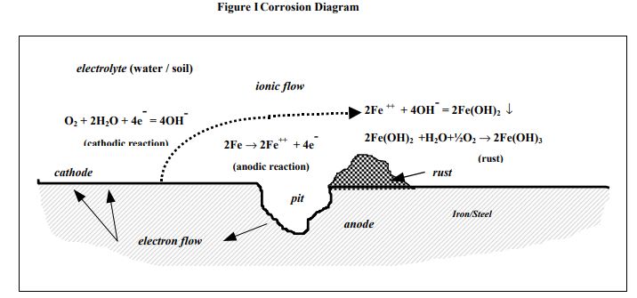
2.2 Cathode
The CATHODE is the area where corrosion does not occur. Sometimes it can be characterised by the formation of white deposits on the metal surface. Cathodes occur where there is water and oxygen present at the metal surface and react with electrical current flowing in the pipe: the reaction produces an alkali. Of course, the reaction can only occur if the electrons can react with the water and oxygen, in other words there has to be a bare metal surface for this to occur. Note that conventional current flow, as used in this paper, is opposite in direction to electron flow.
2.3 Anode
The anode is the area where corrosion occurs. Anodes frequently occur where there is a low concentration of oxygen in the environment. At the anode the steel dissolves to form rust, and producing electrons that flow in the steel to the cathode. Of course the reaction can only proceed if the metal can react with the alkali; in other words there again has to be a bare metal surface, for example a coating defect, for this to occur.
2.4 Corrosion Voltage
A voltage is required to cause the electrical current to flow between the anode and cathode, and there are a number of sources of the voltage. All metals when placed in water or moist soil adopt a characteristic electrical potential. This potential varies with the type of metal, how corroded it is, how much oxygen and water can get to the metal surface, and a number of other factors. When two areas on a metal structure have different potentials there is a voltage difference, and corrosion currents can flow.
The actual corrosion current is dependent upon the corrosion voltage and the conductivity of the environment, whether it be soil or water. The more conductive the environment, the lower the resistance in the corrosion circuit, and the more rapidly corrosion will occur. The high conductivity of some clay soils can cause very high corrosion rates.
The problem with watermains, as opposed to say driven piles, is that the entire structure is buried in a backfilled environment. Backfill is not as compacted as natural soil and so, amongst other things, can contain a high level of oxygen, which can lead to a far higher rate of corrosion on mains than on driven piles, as the oxygenated areas provide cathodic areas of high driving force for corrosion in the adjacent anodic areas.
The different sources of voltage include:
• The chemical environment of the pipeline – in other words the oxygen and water concentration which can cause
corrosion voltages of about 0.3 volts.
• Galvanic effects from different metals connected to the pipeline – a galvanised (zinc coated) steel service (albeit rare these days) connected to a steel or cast iron main has an anodic driving corrosion voltage of about 0.3 volts causing the galvanised steel to corrode. A copper service off a steel or cast iron main has a cathodic driving corrosion voltage of about 0.5 volts causing the cast iron watermain to corrode. For at least 20 years, copper services have been insulated from iron watermains to prevent this voltage from causing failures.
The above two corrosion mechanisms can cause pipeline perforation to occur in a period of around 20 years, although there will be some far more corrosive areas and some far less corrosive areas(3) .
2.5 Anode/Cathode Separation
The size and separation between anodes and cathodes can vary enormously. For example a stone in contact with the pipe has a cathode in the immediate area of the contact, and an anode at the actual point of contact. The corrosion pitting occurs at the actual contact point between the stone and the pipe where oxygen cannot get access.
At the other extreme, with railway stray current corrosion, there can be many kilometres between the cathode (where the current flows onto the main), and the anode (where current flows off the main and corrosion occurs). Note that conventional current is opposite in direction to electron flow.
3. Cathodic Protection
Cathodic protection works by artificially causing sufficient electrical current to flow onto a metal surface so that it overcomes any possible discharge of current from that surface, thus preventing corrosion. There are two methods of applying cathodic protection:
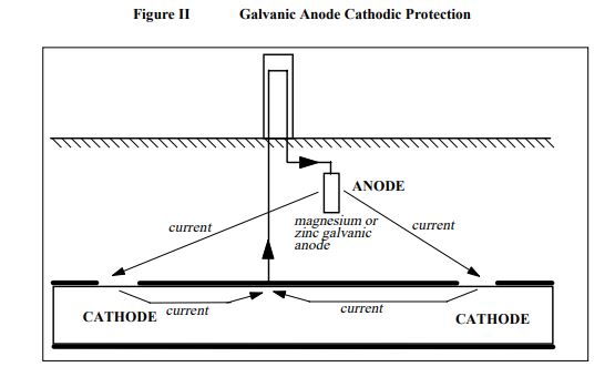
a. Galvanic anode cathodic protection
This is achieved by installing magnesium or zinc anodes in the ground near the pipeline, or within the reservoir, and connecting them to the structure. This is called galvanic anode cathodic protection. Magnesium and zinc are much more active metals than steel as they have a high cathodic driving voltage to steel.
The corrosion voltage to steel for magnesium is about 0.6 volts, and for zinc is about 0.2 volts. These metals become the anode and corrode to protect the steel from corroding itself as shown in Figure II.
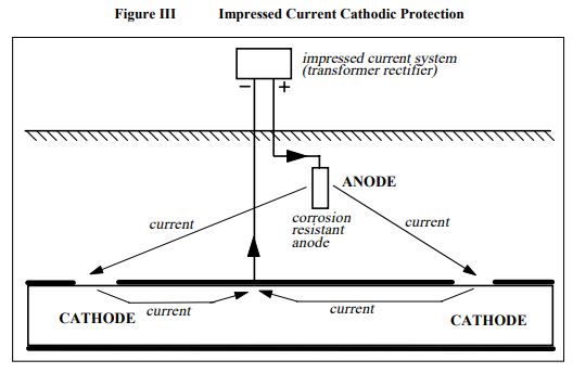
b. Impressed current cathodic protection
An impressed current cathodic protection system shown schematically as Figure III, obtains its voltage to prevent the corrosion from an external power supply, typically mains power. The anodes do not corrode because they are made from such corrosion resistant materials as platinum, semiconductor oxides, or an alloy of chromium-silicon-iron.
The driving voltage used with these anodes is limited, by personnel safety considerations, to 50 volts. Due to the high operating voltage, these systems can output equally high levels of current and are suitable for large or poorly coated structures, or high resistivity environments. However care is required as under such conditions they may cause interference to other buried structures.
4. Stray Currents
4.1 General
Where direct current flows onto a structure cathodic protection may be achieved. Where direct current flows off a structure, into water or the earth, then corrosion may occur.
Whilst stray current problems can occur within reservoirs and treatment facilities, they occur predominantly on well-coated mains.
Due to the number of variables associated with the determination of the extent of exposure to stray current effects, the following criteria for exposure are indicative only. For a better evaluation of the risk specialist advice should be obtained.
4.2 DC Railway Stray Current
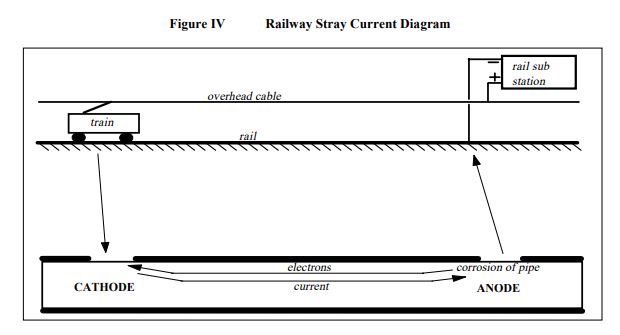
Some railway systems, such as those in Sydney and Melbourne, operate with direct current and use the driven rails as a return path for the current. The positive pole of the rail substation is connected to the catenary, the overhead cables which supply power to the trains. The power passes through the train motor and returns to the negative pole of the substation via the rails upon which the train travels.
However as the rails are not perfectly insulated from earth, a portion of the current can discharge from the rails, travel through the earth, and charge back onto the rails at a remote location. The current which travels through the earth can be picked up on buried pipes at coating defects, travel along the pipe, and then be discharged through coating defects. Where positive current charges onto the pipe the pipe experiences a measure of cathodic protection. Where positive current discharges from the pipe the pipe can experience a rapid rate of corrosion. This is shown in Figure IV.
The location of the current charging and discharging locations can constantly vary. Corrosion voltages can be in excess of 10 volts, and pipe perforation can occur in a matter of months. The stray current corrosion problem can be overcome by the application of cathodic protection and/or stray current drainage, depending upon the magnitude of the problem.
Factors that affect pipeline exposure to stray current corrosion are:
a) Location of the main
• In general the closer the main is to the rail the greater will be the exposure. Severe effects could be expected even on short welded steel main located within 100 metres of the electrified rail. Marginal effects could be expected if the short welded steel main does not approach closer than 5 kilometres of the rail and there are no low resistance return paths to rail. Problems may be anticipated on any long welded steel main laid within the Sydney, Melbourne, or Newcastle metropolitan areas.
b) Electrically continuous length of the pipeline
In general the longer the electrically continuous length of the pipeline the greater will be the magnitude of the potential stray current corrosion. A one kilometre long pipeline in the Sydney or Melbourne metropolitan areas would be expected to experience significant stray current problems. A single isolated pipe length, such as with a rubber ring jointed pipeline, would only experience problems if it were very close to the rail, say within 100 metres or less.
c) Coating quality
The higher the quality of the coating, the more the main will be affected by stray currents. Poorly coated mains tend to be well earthed and have less of a problem. The size, shape, location and number of coating defects in the coating will affect the amount of stray current the pipeline will pick up, and the corrosion rate when it discharges the current. Thus, uncoated grey and ductile iron watermains are rarely at any real risk.
For stray current to cause a corrosion problem there must be at least one coating defect in an area of current pickup and at least one coating defect in an area of current discharge. With a well-coated, long electrically continuous main, say over 1 kilometre in length, such defects can be expected to exist. With well-coated short isolated pipe lengths, such as with polyethylene coated rubber ring jointed steel pipe, such a damage geometry is unlikely.
d) Environment resistivity
The more conductive the environment immediately adjacent to the coating defects the higher will be the discharge current density and the corrosion rate. Conductive soils in current pick up areas increase the current pick up and thus increase current discharge and corrosion rate in current discharge areas.
4.3 Telluric Effects
When the magnetic field around the earth is disturbed as a result of solar storms, or other solar events that cause a variation in the flow of charged particles from the sun into space, a current flows in the earth’s crust. This current can charge onto, and discharge from, buried mains in the same manner as described for DC railway stray currents above. Corrosion can occur at locations where positive current discharges from the pipe surface(1) .
Telluric effects can be overcome by applying constant potential closed-loop controlled cathodic protection systems at specific locations on the main. The output of the cathodic protection unit varies to keep the pipe potential in the protected range.
Factors that affect pipeline exposure to telluric stray current corrosion are:
a. Location of the main
There are a number of location and orientation parameters that can be used to estimate the magnitude of telluric effects on a main. However there are so many anomalies that can over-ride the general assumptions in the models that significant telluric effects can be experienced on a main whatever the its location and orientation parameters.
b. Length of the main
In general the longer the electrically continuous length of the main the greater will be the magnitude of the telluric effects. Significant effects are unlikely on electrically continuous mains less than 50 kilometres in length.
c. Coating quality
The higher the quality of the coating the more the main will be affected by stray currents. Poorly coated mains tend to be well earthed and have less of a problem. The size, shape, location and number of coating defects in the coating will affect the amount of stray current the pipeline will pick up and the corrosion rate when it discharges the current.
For telluric effects to cause a corrosion problem there must be at least one coating defect in an area of current pickup and at least one coating defect in an area of current discharge. The pick up and discharge areas are usually at the ends of electrically continuous sections of pipeline. With a long electrically continuous pipeline, say over 50 kilometres in length, such defects can be expected to exist.
d. Environment resistivity
The more conductive the environment immediately adjacent to the coating defects the higher will be the discharge current density and the corrosion rate. Conductive soils in current pick up areas increase the current pick up and thus increase current discharge and corrosion rate in current discharge areas.
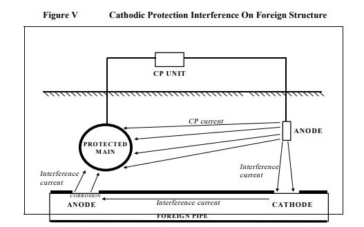
4.4 Cathodic Protection Interference
When cathodic protection is applied to a buried structure, positive direct current flows from the groundbed through the soil and onto the exposed metal of the structure at coating defects. If another buried metallic structure is in the vicinity of the groundbed then some of the current may charge onto it near the groundbed and discharge from it at a remote location. Where the current discharges from it a rapid rate of corrosion can occur. Corrosion can also occur
where the pipe is very close to a poorly coated cathodically protected structure(2). Interference is shown in Figure V.
The two areas of possible effect are:
Groundbed effect – The extent of the groundbed effect increases with increasing current output from the groundbed, increasing soil resistivity in the area, length of the main and its proximity to the groundbed. Unless the groundbed current is high or the soil resistivity high, it is unlikely that significant interference would be experienced if the closest approach of an electrically continuous main to a groundbed is more than 100 metres.
Groundbed locations and operation parameters should be checked with the State Electrolysis Committee. With well coated electrically short lengths of main, as with polyethylene coated rubber ring jointed steel, there is unlikely to be an interference problem from groundbeds unless they are very close.
Structure effect – Unless the protected structure is very poorly coated or has a very large coating defect in the immediate area and the main is very close to it, say within 5 metres, there is unlikely to be an interference problem on the main.
Interference problems have to be resolved by the party causing the interference.
The options for resolving interference are either to apply cathodic protection to the main, to bond it to the structure causing the interference, or to have the owner of the structure causing the interference to turn the CP system off or at least reduce the current output.
5. Water and Sewer Mains
5.1 History
The water industry, with a generally ageing asset base, has a mixture of ferrous construction materials used at various times for trunk and reticulation water main networks:
a. Cast iron
Grey cast iron accounts for about 70% of the existing water main asset base. Grey cast iron was generally replaced by ductile iron from 1976.
Until the mid 1960’s, effective coatings on cast iron pipes were non-existent, and the loose polyethylene sleeving (LPS) employed after this date was highly effective for corrosion prevention(3) , but useless for application of CP as the ‘coating’ was by deliberate design entirely disbonded. However it is so effective in controlling corrosion that CP is generally not required.
b. Steel
Steel pipes were initially constructed as lead-jointed ‘locking bar’ trunk mains, but by the 1930’s welded mains were supplanting their use, and became the default material for trunk mains by the 1950’s. By the 1980’s, rubber ring jointing (rrj) systems had improved and mains were either laid with rubber ring or welded construction systems.
Both systems are available with high quality sintered polyethylene coatings and cathodic protection has been increasingly applied to the welded steel mains. In some cases the rubber ring jointed mains have been provided with cable bonds around every joint and cathodic protection applied(4), although this is rare and usually rrj pipes do not require CP.
5.2 Poorly Coated Rubber Ring Jointed Pipe
The cathodic protection of poorly coated rubber ring jointed pipe usually involves the retrofitting of cathodic protection to an existing main. This is usually only required in very corrosive soils such as saline mud flats, clays containing active bacteria that induce corrosion, and other unusual conditions. There are limitations in the application of cathodic protection to poorly coated rubber ring jointed mains:
a. Bonding
For the cathodic protection current to flow along a main from the anode connection point to the areas where cathodic protection is required, the main must be electrically continuous. For cathodic protection to flow along a rubber ring jointed main, the joints must be electrically bonded over.
On an existing main this requires excavating every joint and installing bonding cables, which presents a significant expense, plus the inherent uncertainty that such bonds will not themselves provide potential failure sites.
b. Coating effectiveness
The light coating of bitumen applied to most older rubber ring jointed cast iron pipe does not provide a good insulating coating to the main and so relatively high cathodic protection currents are required for protection.
However, only relatively low cathodic protection currents can generally be applied to mains as high currents can cause unacceptable interference, which is limited under state laws. However, if the main is in very conductive soils (which are usually the most corrosive), and it is not close to other buried metallic structures, cathodic protection can very occasionally be justified.
c. Loose polyethylene sleeving
Loose polyethylene sleeving is not an effective coating to use with cathodic protection, as, despite its generally good corrosion control performance, it is not designed as an adherent coating.
The cathodic protection current would have a very high resistance path to flow from the point of damage in the sleeving to all of the potential corrosion areas. To benefit from cathodic protection any structure requires an adherent coating.
d. Isolation
To prevent high cathodic protection currents flowing to the electrical earths associated with pumping stations and other structures, insulating flanges have to be installed. To effectively isolate the main a section of the internal surface of the main also requires an insulating lining.
The effect of the lining is to prevent corrosion of the internal surface of the main where cathodic protection current may flow around the insulating flange via the water within the pipe. Where the current discharges from the non-cathodically protected internal pipe surface it can cause corrosion.
5.3 Well-Coated Steel Pipe and Cross-Bonded Rubber Ring Jointed Pipe
In general, well-coated welded steel mains should be cathodically protected. Their electrical continuity results in susceptibility to stray current effects, where rapid corrosion perforation can occur at any coating defects if not provided with cathodic protection.
The long electrical continuity can also result in the electrically continuous section of main spanning soils of high and low oxygen content; such as sandy soils and clay soils. The water main in the high oxygen soils becomes the cathode and causes rapid corrosion of the main in low oxygen soils, which has become the anode. Cathodic protection is required to resolve this risk.Cathodic protection can be applied to rubber ring jointed mains if the environment warrants additional protection and this is achieved by bonding across every joint. Whist it is less expensive to lay rubber ring jointed steel and the provision of bonding at joints so that cathodic protection can be applied, it must be recognised that this imposes a cost penalty and there is an ongoing monitoring and maintenance requirement to ensure that the bonding remains intact.
5.4 Poorly Coated Welded Steel
The effective application of CP to poorly coated steel mains is usually prevented by interference as the high currents required tend to cause interference to other buried metallic structures in the area. If the main is in very conductive soil,
and is remote from other buried structures, CP may be feasible.
6. Tanks and Reservoirs
6.1 History
Above ground reservoirs became common in the 1920’s with both steel reinforced concrete, and riveted iron and steel reservoirs in use. The former were often badly designed with insufficient reinforcement steel, whilst the latter were rapidly superseded in the 1950’s with welded structures. The default internal protective coating for all steel reservoirs up until the 1970’s was hot applied bituminous enamel, and cathodic protection was rarely provided.
In recent times a variety of coatings have been employed, usually solution vinyl or epoxy based, and CP has become normal practice at least in some of the major metropolitan areas.
6.2 Concrete
At first sight, concrete reservoirs would be expected to have few corrosion problems. However, corrosion of the reinforcing steel can cause significant problems, particularly if the design did not provide sufficient steel to cater for bending moments when the reservoir is full.
Even without reinforcement corrosion, many concrete reservoirs crack, causing unacceptable leakage, due to insufficient or poorly designed reinforcement steel. Methods to combat this type of failure using elastomeric coatings have been successfully trialed(5) .
For corroding concrete reservoirs it is quite practical to use CP as a secondary backup (the primary being repair) in the same way as is used in other concrete structures.
6.3 Coated Steel Reservoirs
Older-style riveted and welded steel reservoirs can occasionally still have the original bituminous enamel coating. In most cases these coatings will be extensively disbonded, but this is not evident from a simple visual examination.
CP tests on the full reservoir can reveal the extent of coating disbondment and can be an effective tool for coating integrity assessment.
Modern coatings, such as the now-discontinued vinyl VR3 systems or epoxy coatings are less likely to show significant disbonding unless severe application problems were experienced. The vinyls are susceptible to solvent entrapment, particularly as reservoirs are almost invariably recoated in winter under low ambient temperature conditions. Even though epoxies have limitations with overcoating, they are the preferred coating.
With large (>1Ml) reservoirs the application of high-build epoxies over freshly blasted steel is not practical because the areas to be coated are too large to be blast cleaned and coated in the same day, and the epoxy will not cure sufficiently overnight to allow continued blast cleaning the next day without contamination. As a result an epoxy primer must be used, with application of the high build epoxy on a later day. This introduces a risk of epoxy/primer lamination.
The use of CP on the internal surfaces of well coated reservoirs is now standard practice, with a typical large reservoir (>5ML) using an impressed current cathodic protection system with mixed metal oxide anodes, a constant potential cathodic protection unit,
and protection monitoring with polarisation cells or resistance probes. This level of sophistication is to minimise maintenance of the CP itself and maintain system integrity.
For smaller tanks and reservoirs it is still possible to maintain this level of protection, however it will be a simpler system.
Small well-coated tanks and reservoirs typically use a magnesium anode CP system. Care in design is required with tanks that are rapidly filled and emptied due to the high levels of turbulence, which reduce protection levels.
Impressed current systems provide better control of high current demands as a result of turbulence, and have the ability to cater for increasing percentages of coating breakdown with time. They are more complex and have higher capital cost than galvanic anode systems. A typical impressed current CP system for a well-coated reservoir of 45Ml will cost $40k-$50k to install, compared with internal coating costs for the same reservoir of $250k-$500k.
Galvanic anode systems provide less flexibility than impressed current systems, however they involve significantly less capital cost. The CP for a small 0.1Ml tank might cost less than $5k including installation and commissioning.
7. Water and Wastewater Treatment Facilities
7.1 New Structures
The type of corrosion protection required by any new water or waste water plant will largely depend on:
• Plant design
• Local microclimatic conditions
• Chemical composition of water/effluent
Some of the influences of these variables on materials engineering aspects of plant design have recently been discussed(6) . However, experience shows that immersed structures are best designed in concrete, engineering plastics or corrosion resistant materials such as stainless steel.
The use of coated mild steel explicitly accepts the need for maintenance, whether CP is applied or not. Whole-of-life costing shows that this is not a financially attractive option over a typical 40 year life cycle.
It should be emphasised that CP itself requires ongoing monitoring and maintenance if it is to be effective. Given the added difficulty of many water and waste water plants in being exposed to highly turbulent operation, partially immersed structures and moving components, CP is in general not recommended.
7.2 Existing Structures
In many cases it is necessary to retrofit old plants with CP, especially where there are significant areas of coated or galvanised mild steel in full or partial immersion. This can often include substantial structures such as flotation tanks, trickling filters etc.
The structures can be complex moving structures which are difficult to recoat and even more difficult to effectively apply CP. Nevertheless, this can still be an effective tool. Complications such as a mixture of coated mild steel and bare stainless steel components are often the rule rather than the exception, frequently connected to the reinforcement in a concrete tank.
Hence, design and testing of CP of such structures can typically be a larger component of total cost than is otherwise normal. To overcome some of these problems relatively complicated systems may be required and both capital and operating costs may be high: it is a result of this experience that the use of alternative materials on new structures was recommended in Section 7.1.
8. Cathodic Protection Monitoring
8.1 General
Cathodic protection systems require regular monitoring to ensure their effective operation.
There are two monitoring requirements:
• To ensure that the equipment is functioning.
This requires checking current, voltage of CP units, and current of galvanic anodes.
• To ensure that protection is achieved.
This usually requires a potential survey of the structure.
The requirements for the monitoring varies with the type of cathodic protection system and the environment:
a. Galvanic anode systems
A properly designed galvanic anode system provides long term reliable protection over periods of up to 20 years.
They usually only require annual monitoring to:
• check that none of the anodes has become open circuit (on watermains, this is often caused by excavation by third parties).
• monitor their reduction in performance as they are corroded away.
• ensure that the structure is protected and that there has been no change to its protection parameters.
b. Impressed current systems
Due to the sensitivity of impressed current system electronics to electrical surges that may be picked up by the structure and transmitted to the cathodic protection unit, and other sensitivities, the cathodic protection units should be checked to ensure that they are functioning and are operating within the required parameters every three months.
Annually the structure should be subject to a potential survey to ensure that it is protected and that there has been no change to its protection parameters.
c. Mains in stray current areas
Due to the high corrosion rates that can occur in stray current areas, if there is a problem with the cathodic protection unit it should be addressed as a matter of urgency.
As a result the operation of the cathodic protection units should be checked at not less than monthly intervals. Also as the stray current patterns can vary with time, the main should be subject to a potential survey at not more than 6 monthly intervals.
8.2 Potential Measurements
Test points are used for monitoring cathodic protection effectiveness. They provide electrical access to the structure at a fixed location. On a reservoir they may simply be indicated locations for measuring potentials. On mains they typically comprise cables attached to the main and housed in a junction box, every kilometre or so along the route. A potential reading is taken by measuring the potential between the structure and the environment using a high quality multimeter and a reference electrode. If the potential is negative of the protection criterion, –850mV to a copper/copper sulphate reference electrode, the structure is deemed to be protected.
In stray current areas the potential of a main may vary constantly and so recordings of potential have to be taken.
Such recordings are taken with chart recorders or data loggers. The recordings are evaluated to determine whether protection is achieved.
However when the potential of a cathodically protected structure is measured with the cathodic protection system energised, the measurement includes the actual potential of the structure plus a voltage gradient component originating from the passage of the cathodic protection current through the electrolyte(7) . The effect is particularly high in high resistivity soils and in fresh water. This error in the potential reading may be so high as to invalidate the reading. This is a problem with both mains(8) and reservoirs(9) .
When the cathodic protection current is switched off the error will immediately be removed whilst the actual potential of the structure surface will remain and decay over a period of time. Satisfactory measurements of potential can usually be taken within a second following interruption of current flow, however this period of time can vary and is dependent upon a number of factors. Where there is more than one source of a cathodic protection current, all sources that may influence the reading have to be switched at the same time.
8.3 Other Monitoring Techniques
As an alternative to off-potential measurements, coupons and resistance probes can be used to provide a measure of the effectiveness of a cathodic protection system on a well coated structure.
A coupon is a section of metal of similar size to a typical coating defect. It is exposed to the same environment as the structure, and is electrically connected to the structure so that it experiences the same cathodic protection environment.
The coupon potential is measured the instant it is temporarily open circuited from the structure. This provides a potential reading free of electrolyte voltage gradient errors.
A resistance probe element is a section of metal, of a size similar to a typical coating defect, of very thin cross-section. It is exposed to the same environment as the structure, and is electrically connected to the structure so that it experiences the same cathodic protection environment. If the probe element corrodes it loses cross-sectional area and as a result its electrical resistance increases. The loss of metal can be determined from measurements made using a resistance probe measuring meter. The resistance probe method is very sensitive and can monitor very low rates of corrosion.
The coupons or resistance probes should be installed such that the following parameters can be measured:
• For resistance probes, the loss of metal section, measured with the resistance probe instrument, and by inference, the amount of corrosion occurring on the structure
• The cathodic protection current to the coupon or probe element, and by inference, the cathodic protection current density that would flow onto a coating defect on the structure in that area.
• On-potentials and off-potentials on the coupon or probe element.
9. Conclusions
• Cathodic Protection (CP) is a viable tool to use in the water industry provided it is applied only in conditions where economic analysis favours its use over alternative materials strategies.
• In general, retrofit of CP to poorly coated pipelines is likely to be difficult and may produce unacceptable interference to foreign structures.
• CP of new, welded steel pipelines with highly effective coatings is relatively cheap and should be standard industry practice.
• CP of new rubber ring jointed pipelines with highly effective coatings is generally not required and ought not to be standard practice. Conditions requiring CP are best met by welded steel pipelines. CP of rrj pipelines can be achieved in special circumstances but the total costs of such options must be carefully evaluated.
• The monitoring and maintenance costs of CP systems must be part of overall economic assessment of all viable options.
• Steel reservoirs with high quality coatings and relatively constant water levels should have CP applied as standard practice. Lower monitoring costs can be achieved by integrating CP potential/current measurements into telemetry systems.
• The use of CP on corroding steel rebar in concrete reservoirs can be a useful tool.
• CP is not recommended for use in new water or waste water plants where alternative design strategies can eliminate coated mild steel. It can be used retrospectively in existing plants only with difficulty and at relatively high cost.
10. References
1. Martin, BA. ‘Telluric effects on a buried pipeline’ Corrosion 49, 4, p343 (1993)
2. Martin, BA & Huckson, J. ‘New developments in interference testing’ Industrial Corrosion 4, 6, p26 (1986)
3. Ferguson, PH, and Nicholas, DMF. ‘External corrosion of buried iron and steel watermains’ Proc. ACA Conf. 31,
Sydney, (1991).
4. Martin, BA. ‘The limitations of cathodic protection’ Corrosion Australasia 11, 1, p12 (1986)
5. Nicholas, DMF, Shepherd, M. ‘Use of elastomeric materials in sealing concrete reservoirs’ ACA Conf., Auckland,
NZ, (1990).
6. Nicholas, D, Moore, G. ‘Materials engineering in water and wastewater treatment plant design’ AWWA 18th
Federal Convention, Adelaide, (1999).
7. Martin, BA. ‘The ohmic component of potential measurement’ Materials Performance 20, 1, p52 (1981)
8. Martin, BA. ‘Potential measurement on buried pipelines’ Ch17 ‘Cathodic Protection Theory and Practice’,
published Ellis & Horwood, UK. (1986)
9. Nicholas, D & Cunneen, G. ‘Cathodic protection of potable water steel reservoirs’ Proc ACA Conf 25, Newcastle.
(1985)